Laterizio: Difference between revisions
Jump to navigation
Jump to search
(→uC) |
|||
| (15 intermediate revisions by the same user not shown) | |||
| Line 1: | Line 1: | ||
'' | [[Category:Radio]] | ||
''mo/demodulatore ssb digitale'' | |||
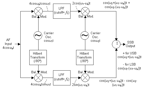
'''laterizio''' e' un modulatore e demodulatore per SSB a metodo weaver implementato su un DSP a basso consumo, per RTX radio portatili | |||
In ricezione, i segnali complessi I e Q vengono campionati simultaneamente su due ADC con risoluzione di 10bit e frequenza di 20Khz, filtrati con un filtro FIR, e moltiplicati con un oscillatore numerico in quadratura. I due segnali vengono poi sommati o sottratti a seconda della banda laterale desiderata. | |||
[[File:Image007.gif]] | |||
* http://www.hanssummers.com/weaver.html | |||
* http://stor1.nonoo.hu/hamdsptutorial/weavermethod.pdf | |||
== uC == | == uC == | ||
| Line 10: | Line 20: | ||
* UART: 2 | * UART: 2 | ||
* primitive DSP | * primitive DSP | ||
* ADC | * ADC 10/12bit | ||
* DAC | * DAC 16bit | ||
Usa il layout di [[CodecBoard16]] | |||
possibili alternative: | |||
* http://www.st.com/content/st_com/en/products/microcontrollers/stm32-32-bit-arm-cortex-mcus/stm32f3-series/stm32f373.html?querycriteria=productId=LN10 | |||
== Letture == | == Letture == | ||
Phasing method: | |||
* http://www.ece.umd.edu/~tretter/commlab/c6713slides/ch7.pdf | * http://www.ece.umd.edu/~tretter/commlab/c6713slides/ch7.pdf | ||
* http://www-inst.eecs.berkeley.edu/~ee120/fa99/notes/notes15.pdf | * http://www-inst.eecs.berkeley.edu/~ee120/fa99/notes/notes15.pdf | ||
| Line 91: | Line 42: | ||
* http://forums.parallax.com/discussion/132977/hilbert-transform-prop-dsp | * http://forums.parallax.com/discussion/132977/hilbert-transform-prop-dsp | ||
* http://www.dsprelated.com/showarticle/176.php | * http://www.dsprelated.com/showarticle/176.php | ||
Weaver method: | |||
* http://dp.nonoo.hu/projects/ham-dsp-tutorial/11-ssb-weaver/ | |||
* http://home.comcast.net/~w1qg/fpga_dsp1.pdf | |||
* http://www.radioexperimenter.us/re-09-1993/a-weaver-method-ssb-modulator-using-dsp.html | |||
* http://www.microtelecom.it/ssbdex/ssbdex-e.htm | |||
* http://homepage.ntlworld.com/johngduffy/Project/Chapter2.htm#Multi | |||
* http://zimmer.fresnostate.edu/~pkinman/pdfs/Receiver%20Architectures.pdf | |||
* http://cdn.intechopen.com/pdfs/9961/InTech-Receiver_front_end_architectures_analysis_and_evaluation.pdf | |||
Latest revision as of 13:55, 28 September 2016
mo/demodulatore ssb digitale
laterizio e' un modulatore e demodulatore per SSB a metodo weaver implementato su un DSP a basso consumo, per RTX radio portatili
In ricezione, i segnali complessi I e Q vengono campionati simultaneamente su due ADC con risoluzione di 10bit e frequenza di 20Khz, filtrati con un filtro FIR, e moltiplicati con un oscillatore numerico in quadratura. I due segnali vengono poi sommati o sottratti a seconda della banda laterale desiderata.
uC
http://www.microchip.com/wwwproducts/Devices.aspx?dDocName=en532298 dsPIC33FJ128GP802
- RAM: 16K
- Flash: 128K
- Timers: 5
- UART: 2
- primitive DSP
- ADC 10/12bit
- DAC 16bit
Usa il layout di CodecBoard16
possibili alternative:
Letture
Phasing method:
- http://www.ece.umd.edu/~tretter/commlab/c6713slides/ch7.pdf
- http://www-inst.eecs.berkeley.edu/~ee120/fa99/notes/notes15.pdf
- http://www.katjaas.nl/hilbert/hilbert.html
- https://www.ece.uvic.ca/~elec350/lab_manual/data/SSB_theory.pdf
- http://www.dg5mk.de/pages/artikel/content-in-english-language/fft-ssb-modulation-and-demodulation---how-it-works.php
- http://tlfabian.blogspot.it/2013/01/implementing-hilbert-90-degree-shift.html
- http://rheslip.blogspot.it/2014/04/teensy-sdr-implementing-image.html
- https://it.mathworks.com/help/signal/examples/single-sideband-modulation-via-the-hilbert-transform.html
- http://www.moetronix.com/dspic/
- http://ae6ty.com/Papers_files/SDR-QrpQuarterly-Part-3.pdf
- http://forums.parallax.com/discussion/132977/hilbert-transform-prop-dsp
- http://www.dsprelated.com/showarticle/176.php
Weaver method:
