Ondeggiatore: Difference between revisions
| (20 intermediate revisions by the same user not shown) | |||
| Line 1: | Line 1: | ||
[[Category:Radio]] | [[Category:Radio]] | ||
''VFO & controller per ricevitori a conversione diretta (e non)'' | ''VFO & controller per ricevitori a conversione diretta (e non)'' | ||
== Codice == | |||
http://nebbia.esiliati.org/repos/cesco/ondeggiatore/ | |||
== Interfaccia == | == Interfaccia == | ||
| Line 12: | Line 16: | ||
=== display === | === display === | ||
* 16x2 | * ST7032i 16x2, 3.3v, SPI | ||
* 3.3v | * ST7032i 16x2, 3.3v, I2C | ||
* | * SSD1675A 104x212, 3.3v, SPI | ||
http://www.buydisplay.com/default/16x2-lcd-3-3v-character-cog-display-module-black-on-white | http://www.buydisplay.com/default/16x2-lcd-3-3v-character-cog-display-module-black-on-white | ||
{| | {|style="color:blue; background-color:#ffffdd;" cellpadding="10" cellspacing="0" border="1" | ||
!Pin No. | !Pin No. | ||
!Pin Name | !Pin Name | ||
!Descriptions | !Descriptions | ||
|- | |- | ||
|1||XRESET||External reset pin, Only if the power on reset used, The XRESET pin must be fixed to VDD, Active Low. | |1||XRESET||External reset pin, Only if the power on reset used, The XRESET pin must be fixed to VDD, Active Low. | ||
|- | |- | ||
|2||RS||Select Registers. | |2||RS||Select Registers. 0: Instruction Register(for write) Busy Flag & Address Counter(for read) 1: Data Register(for white and read) | ||
|- | |- | ||
|3||CSB||Chip Select Input Pin. Low Active. | |3||CSB||Chip Select Input Pin. Low Active. | ||
| Line 46: | Line 48: | ||
|10||PSI2B||SI2(IIC):PSB=1,PSI2B=0; | |10||PSI2B||SI2(IIC):PSB=1,PSI2B=0; | ||
|- | |- | ||
|| | |11||CAP1P||Connect capacitors between CAP1P and CAP1N | ||
|- | |- | ||
|| | |12||CAP1N||Connect capacitors between CAP1P and CAP1N | ||
|} | |} | ||
== | == Dispositivi supportati == | ||
=== AD9834 === | === AD9834 === | ||
| Line 65: | Line 67: | ||
http://www.analog.com/en/products/rf-microwave/direct-digital-synthesis/ad9850.html | http://www.analog.com/en/products/rf-microwave/direct-digital-synthesis/ad9850.html | ||
SSOP28, 3.3-5 V, 125Mhz, 10bit, SFDR > 50 dB @ 40 MHz | |||
Usa i piedini DDS_CS, SCK, SDO sul uC | Usa i piedini DDS_CS, SCK, SDO sul uC | ||
==== HC-SR08 ==== | In commercio si trovano gia assemblati due moduli: | ||
==== Modulo con Rset esposta ==== | |||
[[File:AD9850-Module.jpg|foto]] | |||
[[File:9850 DDS rset.jpg|thumb|none]] | |||
==== Modulo HC-SR08 ==== | |||
[[:File:HC-SR08 AD9850 Module.png|schema]] | |||
Piedinatura: | |||
{|style="color:blue; background-color:#ffffdd;" cellpadding="10" cellspacing="0" border="1" | {|style="color:blue; background-color:#ffffdd;" cellpadding="10" cellspacing="0" border="1" | ||
| Line 165: | Line 179: | ||
=== Mappa pin === | === Mappa pin === | ||
Usa il layout di [[CodecBoard16]] | |||
== memoria esterna == | == memoria esterna == | ||
Latest revision as of 21:13, 2 April 2018
VFO & controller per ricevitori a conversione diretta (e non)
Codice
http://nebbia.esiliati.org/repos/cesco/ondeggiatore/
Interfaccia
Input
- up + down
- left + right
- enter+exit
display
- ST7032i 16x2, 3.3v, SPI
- ST7032i 16x2, 3.3v, I2C
- SSD1675A 104x212, 3.3v, SPI
http://www.buydisplay.com/default/16x2-lcd-3-3v-character-cog-display-module-black-on-white
| Pin No. | Pin Name | Descriptions |
|---|---|---|
| 1 | XRESET | External reset pin, Only if the power on reset used, The XRESET pin must be fixed to VDD, Active Low. |
| 2 | RS | Select Registers. 0: Instruction Register(for write) Busy Flag & Address Counter(for read) 1: Data Register(for white and read) |
| 3 | CSB | Chip Select Input Pin. Low Active. |
| 4 | SCL | Clock Input Pin |
| 5 | SDA | Input Data Pin |
| 6 | VSS | GND |
| 7 | VDD | Power Supply |
| 8 | VOUT | DC/DC voltage converter. Connect a capacitor between this terminal and VDD when the built-in booster is used. |
| 9 | PSB | SI4(SPI):PSB=0, PSI2B=1; |
| 10 | PSI2B | SI2(IIC):PSB=1,PSI2B=0; |
| 11 | CAP1P | Connect capacitors between CAP1P and CAP1N |
| 12 | CAP1N | Connect capacitors between CAP1P and CAP1N |
Dispositivi supportati
AD9834
75Mhz, 10bit
Usa i piedini DDS_CS, SCK, SDO
AD9850
http://www.analog.com/en/products/rf-microwave/direct-digital-synthesis/ad9850.html
SSOP28, 3.3-5 V, 125Mhz, 10bit, SFDR > 50 dB @ 40 MHz
Usa i piedini DDS_CS, SCK, SDO sul uC
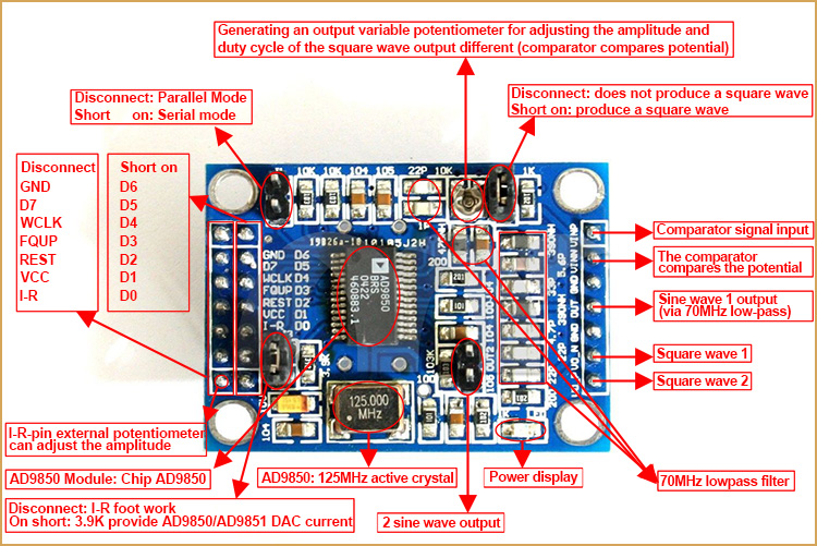
In commercio si trovano gia assemblati due moduli:
Modulo con Rset esposta
Modulo HC-SR08
Piedinatura:
| Pin | Funzione |
|---|---|
| 1 | VCC |
| 2 | W_CLK |
| 3 | FU_UD |
| 4 | SDI |
| 5 | Reset |
| 6 | GND |
| 7 | Square Out 1 |
| 8 | Square Out 2 |
| 9 | Sine Out 1 |
| 10 | Sine Out 2 |
| 11 | GND |
| 12 | D7 |
| 13 | D6 |
| 14 | D5 |
| 15 | D4 |
| 16 | D3 |
| 17 | D2 |
| 18 | D1 |
| 19 | D0 |
| 20 | VCC |
SI570
Si570 CAC000141DG http://www.silabs.com/Support%20Documents/TechnicalDocs/si570.pdf
Fout = (fXTAL * RFREQ)/(HSDIV * N1)
- http://g4oep.atspace.com/si570vfo/570VFO.htm
- http://www.cliftonlaboratories.com/si570_kit_from_k5bcq.htm
Si5351a
https://www.silabs.com/Support%20Documents/TechnicalDocs/Si5351-B.pdf
0.0025 — 200 MHz
Filtro
l'uscita dei DDS va fatta passare per un 'filtro di ricostruzione', che tagli via per quanto possibile le spurie e le armoniche di campionamento del DAC
si puo copiare da questo: http://www.pongrance.com/super-dds.html che pero ha un clock di 80mhz (cambia poco)
o questo http://www.elecraft.com/manual/KX1_Owner%27s_Manual_Rev_E.pdf, che e' tagliato un po piu basso
http://www.analog.com/static/imported-files/application_notes/351016224AN_837.pdf
uC
- riceve l'input dai tasti (6 pin) o dall'encoder (4 + 2)
- riceve l'input da eventuale PTT (shift) (1 pin)
- riceve l'input da eventuale Carrier Detect (per lo scan) (1 pin)
- controlla il LCD (SPI)
- controlla il DDS (SPI) / Oscillatore (I2C)
- controlla la Rset del DDS (1 pin)
- controlla il banco filtri (4 pin)
- controlla la backlight (1 pin)
- si interfaccia con la memoria EEPROM (SPI)
24 pin totali di I/O
- DDS, lcd e memoria esterna possono convivere sul modulo SPI
Mappa pin
Usa il layout di CodecBoard16
memoria esterna
- EEPROM 256 kbit 25LC256 o 25LC512
Connettori
Controllo
| Pin | Funzione | Nome |
|---|---|---|
| 1 | FILTER_1 | |
| 2 | FILTER_2 | |
| 3 | FILTER_3 | |
| 4 | FILTER_4 | |
| 5 | CD | |
| 6 | PTT |
UART
| Pin | Funzione | Nome |
|---|---|---|
| 1 | Massa | GND |
| 2 | Uart tx | TX |
| 3 | Uart rx | RX |
Firmware
Features
- canali con nome alfanumerico su memoria esterna
- bande con nome alfanumerico su memoria esterna
- step (1,10,100,500,1000,1250,2500,5000,9000,10000,50000,100000,1000000) (4 byte) o semplicemente potenze di 10 ? su eeprom interna
- frequenza 0 - 30 MHz su eeprom interna (4 byte)
- shift TX/RX (+- 0 - 30 MHz) su eeprom interna (4 byte)
- IF (+- 0 - 30 MHz) su eeprom interna (4 byte)
- additiva: il display mostra la frequenza dell'IF + la frequenza del VFO
- sottrattiva: il display mostra la frequenza dell'IF - la frequenza del VFO
- scan (volatile)
- dentro banda
- dei canali
- filtri su eeprom interna
- numero (1 byte)
- fmin (4 byte)
- fmax (4 byte)
- phase register su eeprom interna
- frequency register su eeprom interna
- DDS clock
la memoria viene divisa in blocchi da 32byte
ogni nuovo canale/banda viene memorizzato nel primo blocco/canale flaggato come non attivo
quando si naviga tra i canali/bande, vengono letti i blocchi in ordine finche non si trova il successivo canale/banda
Flag
| 00 | non attivo |
| 01 | canale |
| 10 | gruppo |
| 11 | banda |
Canale
| 16-31 | 12-15 | 1 | 0 |
| channel_name | frequency | group_id | flag |
Gruppo
| 16-31 | 1 | 0 |
| group_name | group_id | flag |
Banda
| 16-31 | 12-15 | 8-11 | 4-7 | 0 |
| band_name | band_step | frequency_min | frequency_max | flag |

